SmartDB v2 — permanent compact project
The compact redesign is now the main v2 project in smart_db/.
Open smart_db/smart_db.kicad_pro in KiCad 10.
The former compact_wip/ folder has been moved here with its local libraries,
editing scripts, review outputs and saved history.
Current revision
95 × 78 mm four-layer PCB with an ESP32-S3-WROOM-1-N16R8 module.
Standard construction assumption: 1.6 mm FR-4, 1 oz outer / 0.5 oz inner copper.
AP63203 buck supply, ADC supply filter, decoupling and test points.
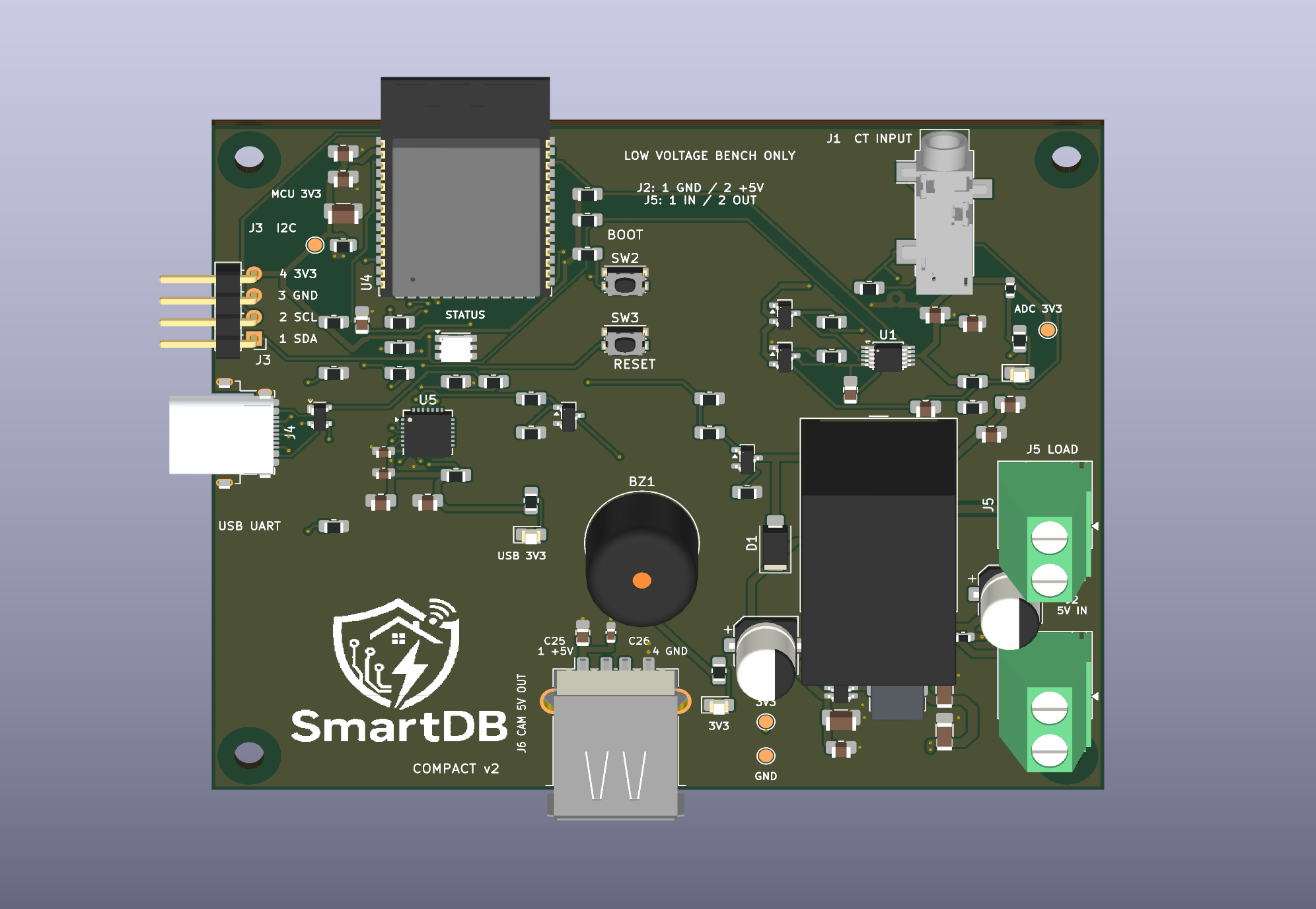
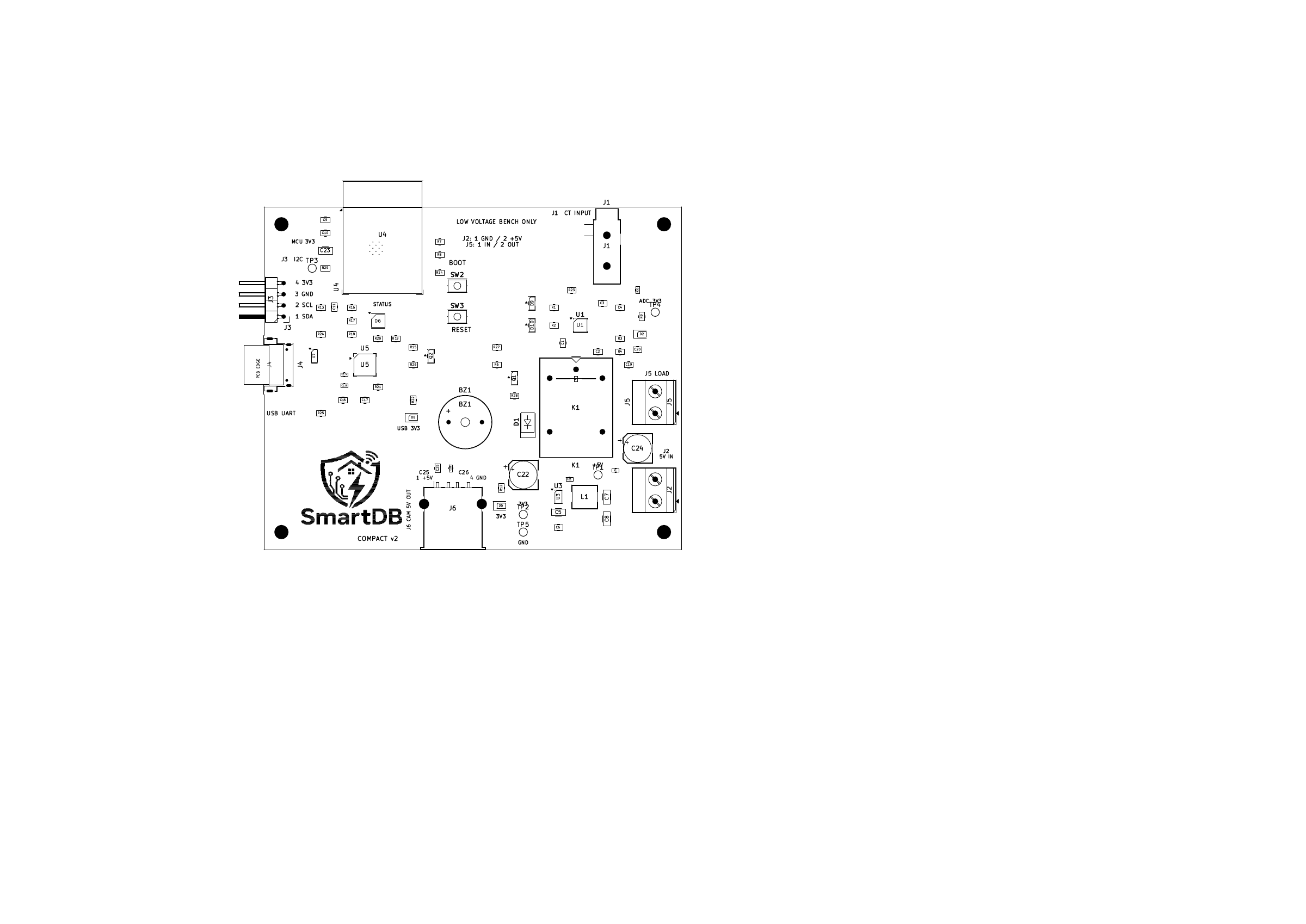
Accessible I²C and USB connectors, front/back pin labels and a SmartDB logo.
Two camera connections: J3 for the MLX90640 thermal module, and J6 USB-A for ESP32-CAM-MB power through a USB-A to micro-USB cable. J6 uses SMD contacts, is fused and locally decoupled, and has no data connection. The two-target firmware provides Wi-Fi JPEG capture and S3 thermal fusion. See the power budget.
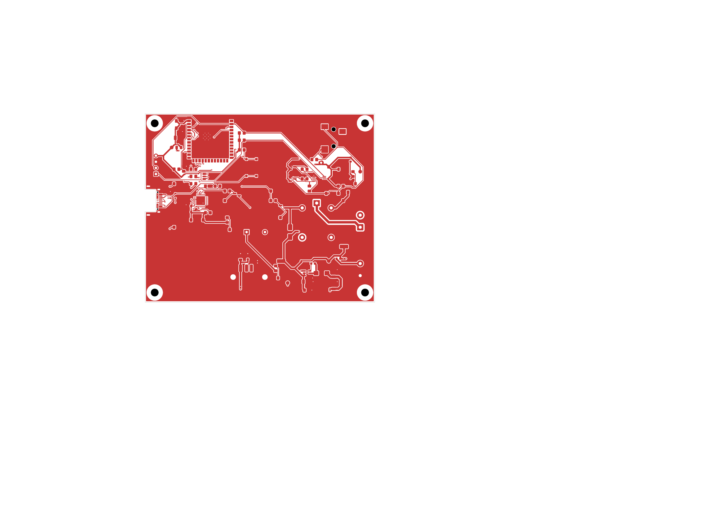
Fully routed board, including the buck converter, ADC, relay, USB/UART and control signals; routing and trace-width review.
Preferred widths: 0.30 mm signals, 0.60 mm power, 0.75 mm 5 V/coil supply, and 1.00 mm load paths, with narrower local escapes where required.
Regulated 5 V logic input; provisional 5–24 V DC, up-to-1 A resistive relay test load.
Routing complete: 0 unconnected items. Engineering review remains before fabrication. KiCad 10.0.6 reports 0 ERC violations, 0 DRC violations and 0 schematic/PCB mismatches. See the project notes for the remaining hardware and stackup validation.
Firmware and setup
Open esp_idf/smartdb_fusion in VS Code and run SmartDB: Setup, or launch ./setup.sh
from that directory. Set up the separate esp32cam board first, then the smartdb_s3
main board. The menu handles firmware installation, Wi-Fi, camera address, protection
limits and status. Connection settings persist on each board without subsequent reflashing.
Use J4 USB-C for main-board programming and connect the camera base directly to the computer for camera programming. J6 is camera power only. The selected SCT-013 firmware monitors isolated low-voltage AC; the logic supply remains DC, and the earlier provisional DC relay load target is not a verified AC contact rating. Firmware builds/host tests pass; physical sensor, relay, power and camera-alignment validation remain pending.
Files and previews
Download the complete current v2 CAD package.
It includes the PCB, schematic, project-local libraries and 3D models, pin map, review
PDFs and validation record. Documentation builds verify every recorded source hash before
packaging; editor lock files, user preferences and historical work directories are excluded.
The bundle is generated by docs/build.sh or docs/prepare_vercel.py.
File |
Purpose |
|---|---|
Editable schematic |
|
Editable, fully routed compact board |
|
Current 3D preview; approximate connector models are not enclosure-fit references |
|
All four copper layers |
|
Current schematic export |
|
Front assembly and logo preview |
|
Connector pin labels |
|
MCU signals and power connections |
|
Source hashes and checks |
Keep SmartDB.kicad_sym, SmartDB.pretty/, sym-lib-table and fp-lib-table
and SmartDB.3dshapes/ beside the project. The library paths are project-relative.
The USB 3D model is an approximate visualization, not an enclosure-fit model.
Previous revision
The previous routed bench board, its schematic PDF, STEP export, review reports,
project history and documentation are preserved in
archive/bench_before_compact_2026-10-08/.
Its routing and validation results apply only to that archived board.
The current system requirements remain in the architecture.